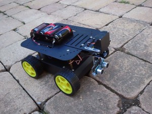
Arduino 4wd robot & Ping))) sensor
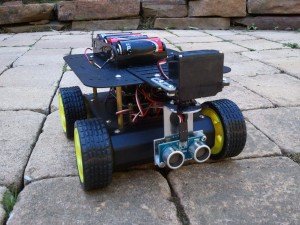
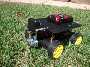
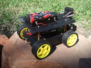
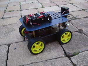
Armed with the knowledge of my previous “Ponar” post, I successfully completed construction and programming of my “Arduino-based 4wd robot with servo-actuated Ping))) sensor”. It was an enjoyable process with a lot of trial and error since: I’m still learning a lot about how the Arduino works, how hardware hooked up to it works, and electronics work in general. To get things started, here is a video of it driving around my kitchen:
Here’s the parts list:
- Arduino Duemilanove (I’m sure any modern Arduino board will work though)
- Adafruit Motorshield
- Paralax Ping))) sensor
- Paralax (Fubata) “standard servo” and mounting hardware
- DFRobot 4wd mobile platform
- Extra 4xC battery holder (6v).
- Extra toggle switch (the robot kit comes with one, I needed two).
Here’s the Arduino program:
How it works:
- I wanted a simple robot to drive around avoiding obstacles using the ping sensor. To do that, I sketched out (on paper) the general program, that went like this:
- Ping to see if there is any obstacles in front.
- If not, drive forward, while pinging.
- If there is an obstacle, stop, and take a distance reading to the left and right of the robot.
- Turn for a fixed period of time in the further direction.
- Ping again: If still blocked, keep turning that direction. If not blocked, go back to drive mode.
- There are basically three modes the robot can live in: Drive forward (mode 1), stop and scan (mode 2), and turn (mode 3). When driving, it can do three things: Drive straight, turn left, turn right.
- The hardware is configured like so:
- The Adafruit Motorshield is plugged into the top of the Arduino.
- The Arduino is powered off of 5xAA batteries (7.5v) in the belly of the robot. These are wired to a switch sticking out the back of the robot.
- The Motorshiled is powered off a separate 4xC battery pack (6v) on top of the robot. These are wired to another switch on the back of the robot.
- The 4 DC wheel motors & servo are powered off the Motorshield.
- The Ping))) sensor draws power form the Arduino.
Things Learned:
- Next time, use 2-wheeled robot instead: easier to steer around the house. The “tank steering” method of this robot seems like it uses a lot of power and doesn’t work very good.
- I read it in a couple places, and it turns out it’s probably needed: Solder a 1uf capacitor between the leads on the DC motors to help “smooth out” their operation. Otherwise it seems little “hiccups” can happen while driving.
- Voltage, voltage, voltage:
- I was having all sorts of problems getting the motors to work properly: They’d start\stop “hiccuping” a lot. Per the above note I added in extra capacitors on the motors themselves, but it didn’t solve all the problems:
- Originally I had the motors hooked up to the 5xAA battery pack (7.5v) that came with the robot chassis. The motors per the specs are rated at max for 6v. But… I didn’t know this. I thought it needed moar power. So I went out and got a 6xC (9v) pack and powered the motors through that. The stuttering got even worse (although, it went pretty fast when it behaved) and even did something really stupid: Put one of the batteries in backwards… which caused it to melt-down and leak acid everywhere. Sigh…
- Finally (after I knew the correct voltage for the motors and servo) I went out and got a 4xC pack (6v), and that, combined with the extra capacitors, finally gave it a smooth ride.
- I had to solder in extra connections to the analog pins on the motorshield to allow fo the Ping))) sensor to passthrough it to the Arduino (acting as a digital pin). However, the motorshield has the pins in the order of “signal\-\+”, while the cables from the Ping))) (and servo) are “signal\+\-“. Not sure why the motorshield would break ordering convention, but I had to splice and re-wire the Ping))) cable to match the board.
- The motorshield docs say that servo2 is pin9, but it’s actually pin10. That took me a while to figure out… :-S
- I ran into a lot of problems with the programming of the robot itself:
- The behavior is to run, ping, scan, repeat. But during “scan” it wouldn’t drive the servo full left\right: Sometimes it would only got left, never make it right.
- To solve this, I put a “timer” in the code, that would only execute the main loop if a certain amount of time in ms had passed (30ms to be exact, which makes it run around 30fps in game terms). This seemed to make it behave exactly how I wanted.
- I thought I needed to tell the motors to run on every loop: It turns out they’re a state machine: once you tell them to run, they keep running until you tell them otherwise. Knowing this helped me clean up the code.
- There doesn’t seem to be any official documentation I could find to the motorshield library, I had to crack open this header file to deduce what it could do: AFMotor.h
Picture time! Click to enlarge:
And a final shot of the wiring on the board per request:
