Posts Tagged ‘ led

Building the C-Bot 3D printer: Part 28 : Lighting, Ringing, Breaking

Jump to C-Bot blog index to see all the posts.


This update is a combo post on several subjects at once:

Adding Lighting

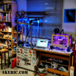
Up until now, the C-Bot has been a dark printer:  No internal lighting whatsoever.  My Replicator1 is like a little supernova next to it when the room is dark.  But no longer:  Over the weekend I added both an 12v LED strip to the top-front X-beam (pointing directly at the print-bed) and a superbright LED directly on the print-head itself:

While my buddy Mason did a slick job of wiring his LED strip directly into the Rumba board on his C-Bot, so he can adjust the lighting based on the print settings, I did not:  I ran a extra 12v lead out of my power-supply, and connected both the LED Strip, and the superbright LED (with inline resistor) directly to it:  Turn C-Bot on, lights turn on.  Nuff’said / good enough.

Breaking

After I installed the lighting and turned the bot back on, the Bowden extruder suddenly started jittering:  It would no longer extrude filament.

I started by swapping a DRV8825 stepper driver from the z-steppers to the extruder stepper slot:  Try extruding, and it works.  Ok, it must be a bad DRV8825, and I have no spares.  But I do have a bunch of extra A4988‘s:  I’ll just put one in there, and updated my firmware to use it instead.  It doesn’t work:  Jittering starts again.  So I revert the firmware change, and put a ‘good’ DRV8825 back in:  Jittering.  What is going on?

Soon, any DRV8825 I put in that slot causes jittering, but they all work when plugged back into their original slot.  Drivers are good,… is my board bad?  At this point I disconnect the 4-prong JST connector running from the board to the stepper, and notice that one side is slightly melted: I remove the wires from the connector, and connect them on-by-one to the pins on the board:  Everything starts working again.

Canibalizing a connector from some other wires, I reinsert the leads, plug it into the board, and back in action.

Seriously?!?

Improving Ringing / Ghosting

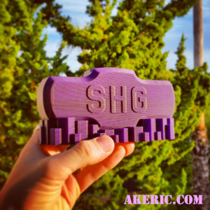
I had recently printed out a “Sledgehammer Games Recognition Coin Holder” for someone at work (I modeled it in Maya / Tinkercad):  We can give out cool coins to fellow employees for doing good work, and I designed this coin holder so people can show them off (there’s four slots in the top to hold the coins).

I’d printed many on my Replicator 1 in the past, and printed this one on the C-Bot for the first time.  And what I noticed was, there was a terrible amount of ghosting / ringing happening:

shg_recognition

Click to see the full-size that really shows the problem off.

This was printed with the .6mm E3D-Volcano nozzle, 300 micron layer heights at 60mm/sec, in MakerGeeks Royal Purple PLA.

The issue was, the prints done on my Replicator 1 had less ringing than the C-Bot, and this didn’t make sense to me:  The C-Bot has a Bowden extruder, thus removing a bunch of moving mass from the toolhead, not to mention it uses Core-XY mechanics, that is supposed to help out as well.  Why are things worse?

Posting this question to the 3D Printing Google Group, I got a bunch of good answers.  Specifically, my firmware acceleration may be too high, and the size of the printer itself could be causing too much shake, do to the lack of additional cross-members for stability.  Right now I have no surplus extrusions to stiffen it up, and my ultimate goal is to bolt the printer directly to the wall, thus really locking down any shaking.  But in the meantime, I can adjust the acceleration in the firmware.

I made a ringing/ghosting test model in Maya that would show off the issue on X, Y, and XY all at the same time.  I printed it with my default settings (3000 mm/sec), then dropped it waaay down to 800 mm/sec.  The results were pretty obvious:

ringing_comparison

Click for bigger pic

On the left of each image, is the ‘800 mm/sec acceleration’ print, and on the right is the ‘3000 mm/sec acceleration’ print.  These changes were made in Marlin’s Configuration.h:

#define DEFAULT_ACCELERATION 800
#define DEFAULT_RETRACT_ACCELERATION 800
#define DEFAULT_TRAVEL_ACCELERATION 800

I just set everything that looked applicable to 800.

So, an noticeable improvement.  But once I get the printer “bolted down”, I hope to be able to print even faster, with better results.


Jump to C-Bot blog index to see all the posts.

New Project: Adafruit Trinket NeoPixel LED Longboard

My son and I recently tackled the “Adafruit Trinket NeoPixel LED Longboard” project: Seemed like it would be a good cross between 3d-printing, electronics, and skateboards.  After running through it though, I found a number of problems with the instructions which I submitted here (if you’re going to do this project, be sure to read them).  Unfortunately at the time of this authoring they haven’t updated their project page to address the problems.

In a nutshell, this is what you need to look out for:

  • Need to order two Neopixel LED strips, not one.
  • There are problems with the wiring instructions, based on missing data.
  • Unless you have ninjaflex or nylon, you may want to entirely skip printing/assembling the front ring enclosures:  I printed mine in solid PLA, and they vibrated apart after the first ride (snapping the internal wiring in the process).
  • If you do print the rings, you really do need to use “wire wrap” to do all the wiring:  Larger gauge wire just won’t fit based on the printed models.  The problem I have with this is although you only need a small amount of wire wrap for the project, it’s best if everything is color coded, and buying wire-wrap in multiple colors actually gets a bit expensive.  I ended up using just two colors, and having to label all the wires (which pretty-much makes it impossible to fix if they snap after everything is assembled).

Overall it was a fun project, just seriously hindered by the confusing instructions, based on other issues I list in the above link.

Here’s the end result before the rings fell apart (and I removed them).  Note the metal bracket over the electronics enclosure and front of the  skateboard:  One jumped curb and you’ll have some smashed equipment without it.

First steps with the Adafruit Trinket

I recently picked up a Adafruit Trinket (3.3v), simply because they’re so cheap (about $8).  I like the idea of a tiny small Arduino-ish board.  Since I’m forgetful, below documents the overall process I got to get it working.

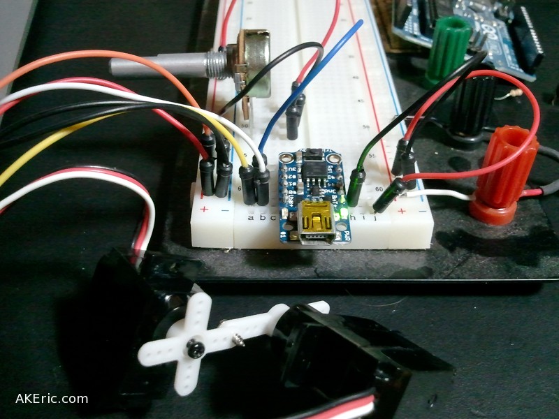
End result:  Franken-servo!

End result: Franken-servo!

Resource Links:

First Steps:

For all the documentation on the web, I really wasn’t sure where to start.  There’s all this talk of installing AVRDUDE, etc, but as it turns out it’s really not needed (if using the Arduino IDE). Here’s the streamline approach I finally took:

  • Setup my pre-existing Arduino IDE for use with the Trinket, following these Adafruit docs.
  • Since I’m on a Mac, I didn’t have to worry about installing any drivers, but the “Mac Arduino IDE” app download they provided didn’t work.  Mac said it was “corrupted”.  So instead I had to use the “Slow Way” example they gave.  And other than a few path differences it worked just fine.

Programming:

  • I was able to successfully run all their examples from the page “Programming with Arduino IDE“.
  • Earlier in the day I had done some servo programming on an Arduino, and I wanted to emulate it on the Trinket.  Thanks to the “Trinket Servo Control” tutorial, and their “Adafruit SoftServo” library, I was able to make it happen.  However, I was unable to create two separate servo objects:  I think I don’t quite grasp the Trinket pinouts.  The above image has two servo’s hooked up to the same pin, so they move the exact same way.

So a successfully first attempt.  Next up, I really need some batteries to make a standalone project with it…

Raspberry Pi WebIDE & making things blink

On the Raspberry Pi, just like on the Arduino, the first thing you learn how to do is make an LED blink.  The Raspberry Pi Users Guide walks you through this process, but this was one of the few areas (so far) with the Pi that I ran into trouble, namely over proper access to the GPIO pins, the Pi Cobbler‘s ribbon-header orientation, and how to physically code on the Pi itself.

Look at that LED blink!

GPIO Pin issues

There appears to be two different ways to access the pins via the RPi.GPIO Python library: Via the ‘board pin numbers’ (1->32), or via the ‘GPIO numbers’, which many sites (like this one) refer to.  In addition, hardware expansions like Adafruit’s Pi Cobbler (which I’m using) base their silk-screens on the ‘GPIO numbers’.  Long story short, you simply need to tell your code ahead of time which method you’re using:
To use the physical board numbers:

import RPi.GPIO as GPIO
# Set to use physical board pin nums, rather than GPIO nums:
GPIO.setmode(GPIO.BOARD)

To use the ‘GPIO’ numbers:

import RPi.GPIO as GPIO
# Set to use GPIO nums, rather than physical board nums:
GPIO.setmode(GPIO.BCM)

Pi Cobbler Issues

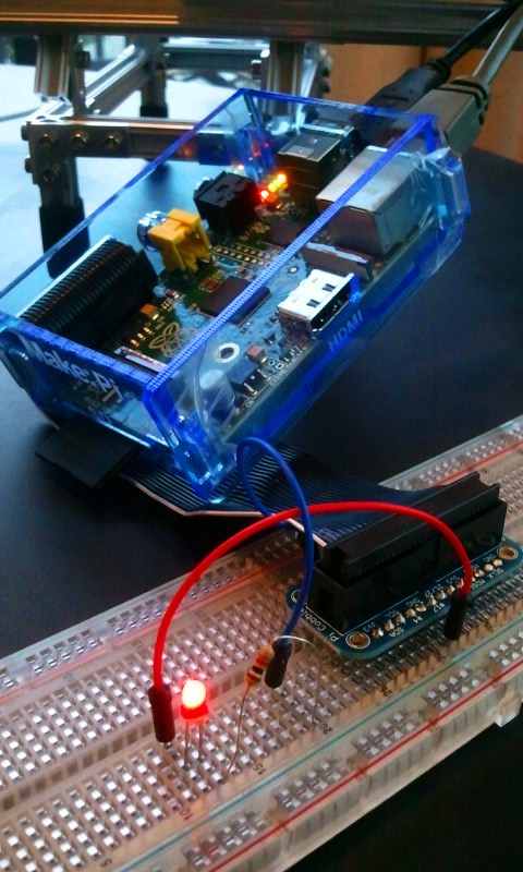
I got the Pi Cobbler via the Maker Shed’s “Raspberry Pi Starter Kit“.  The kit comes with a lot of good stuff to get your started (including the LED that’s blinking next to me).  The Cobbler cable has a header on each end (one plugs into the Pi, one into the Cobbler itself), and each header has a notch on the side to help you understand how to orient it.  At first glance, it looks like the headers are interchangeable… meaning, you could plug either one into the Pi, or the Cobbler.  Very long story short, that’s not true:  To get the side of the cable with the stripe to line up properly with the GPIO pins on the Pi… only one side will work.  I was convinced I had a defective cable that required me to plug it in backwards.  But two days later I realized if I simply flipped the whole cable around everything ‘just worked’.  The Cobbler documentation stresses you insert the cable with the side with the stripe to the left side of the Pi,… but since I thought mine was screwed up…. chaos ensued.  Funny that I didn’t figure this out until I finished this blog post.  The above pic in fact shows the ‘flipped’ insertion in the Pi before I corrected it.

Coding Issues

The final issue I hit was how to actually code Python on the Pi:  I use Wing IDE Professional, and have grown very used to it… but they have no Linux ARM distribution (that I’m aware of).  Going back to IDLE is painful… and I’ve never been a VIM user.  Based on a previous post I can SSH and VNC into the Pi from my Mac, allowing me to code on the mac and copy\paste over to the Pi for execution… but this is still pretty clunky.  After researching for a while I realized, why don’t I try Adafruit’s Raspberry Pi WebIDE?  Installation was easy based on their tutorial, and I was up and running in no time.

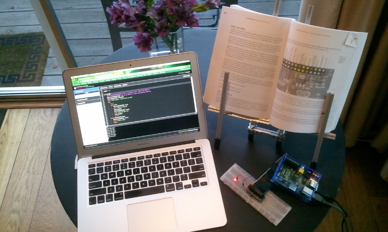
Here is my code to make the LED blink, running in the WebIDE\Pi as I type…

#!/user/bin/env python
"""
gpiooutput.py
Modified from pg 195 of "Raspberry Pi Users Guide"

Make a LED flash on\off.
Hardware Setup:
* LED+ lead hooked to GPIO 17 (board pin 11)
* LED- lead connected to resistor.
* Resistor connected to ground (board pin 6)
"""
import time
import RPi.GPIO as GPIO

# This is the GPIO number.  The actual board pin is number 11.
PINOUT = 17

def main():
    GPIO.setmode(GPIO.BCM) # Set to use GPIO nums, rather than physical board nums
    GPIO.setup(PINOUT, GPIO.OUT)
    print "Blink begins!  Press ctrl+c to exit"
    try:
        i = 1
        while True:
            GPIO.output(PINOUT, True)
            print "Blink %s ON!!"%i
            time.sleep(2)
            GPIO.output(PINOUT, False)
            print "Blink %s OFF!!"%i
            time.sleep(2)
            i += 1
    except KeyboardInterrupt:
        GPIO.output(PINOUT, False)
        print "\nBlink DONE!"
        return

if __name__ == "__main__":
    main()

The WebIDE doesn’t have any fancy features yet (that I’m aware of) like debugging & code-completion, but it is alpha software, so hopefully it will become more robust as time goes on.  On the plus side, it will auto-connect to the Pi over the network (no need for SSH), gives you a built-in terminal for the Pi, and stores all the code  in the cloud via Bitbucket (if you’re into that sort of thing).

And thus, the fruits of my labor:

Raspberry Pi + Pi Cobbler + WebIDE = blinky LED


Eggbot LED Lamp

I’ve had it in the back of my head for a long time to make some type of lamp with LED’s.  And with the arrival of the Ostrich Egg-Bot and its diamond etcher, I had the concept of spray-painting some egg-like object, and etching away a pattern to let light through.  Below is my first attempt at such a thing. Did it work out just like I had envisioned?  Not quite.  But it was a great learning experience, and I’m in a much better place if I decide to do it again.

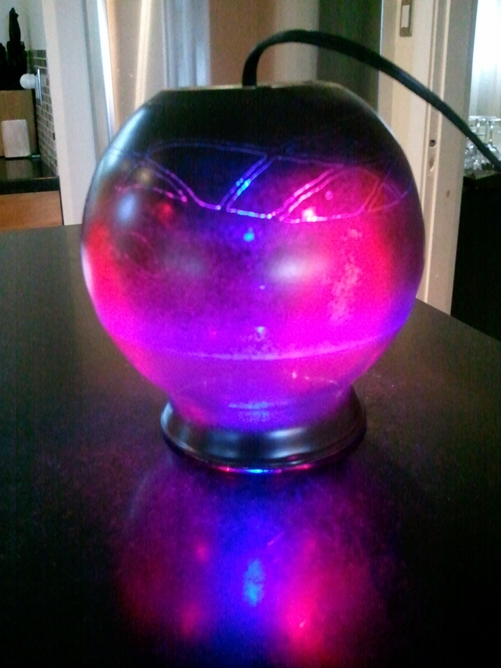
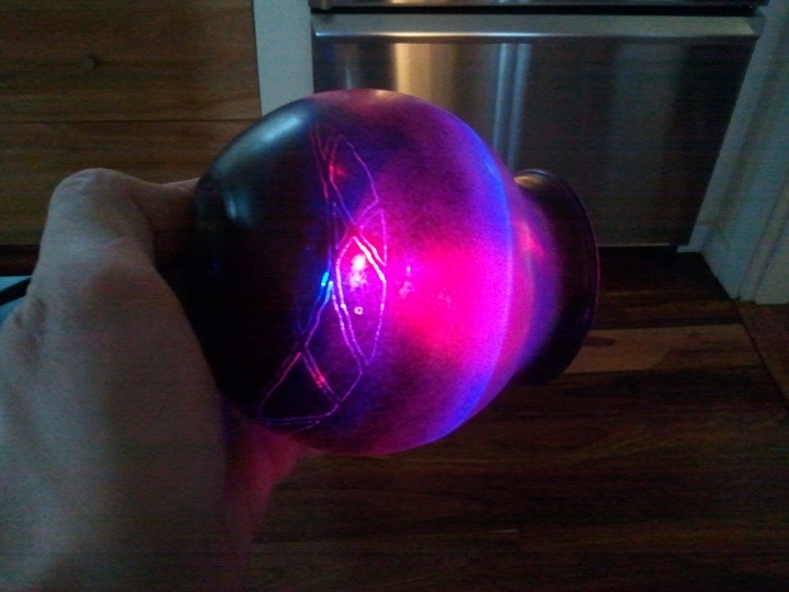
The finished product

I started out by purchasing a simple glass vase at the dollar-store, drilling a hole through its base for the power-cord (which was surprisingly hard even with the special ‘glass drillable bits’ I purchased).  I spray-painted it matte-black on the bottom, and sort of faded the paint up the side so it’d be more transparent at the top.  I designed a simple pattern in Inkscape, which the Ostrich Eggo-bot then etched onto the now-painted glass vase:

Etching in progress...

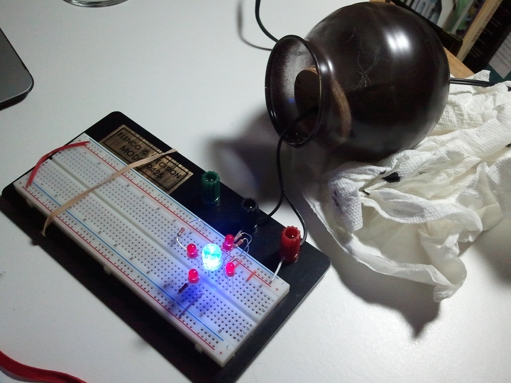
Upon completion of that, I selected four LED’s for the inside of of the light:  A high-power blue for the middle, and four high-power red’s that would shine out the sides.  My hope was the red LED’s would show off the etching.  As a mounting platform for the LED’s I cut a round piece of wood from a piece of scrap plywood, then drilled holes in it for the LED leads, and the power-cable.  I grabbed an old wall-wart, cut off the end, and threaded it through the hole in the vase and my wood disk. I wired that into a breadboard with appropriate resistors:

Breadboard!

Finding success there, I hot-glued the led’s into the wood disk:

From there I started the process of soldering the resistors to the positive leads, twisting all the positive leads together and soldering to the power-cord.  I used black electrical tape as a simple barrier between the positive and negative leads when I soldered second:

Plugged it in to make sure it worked….

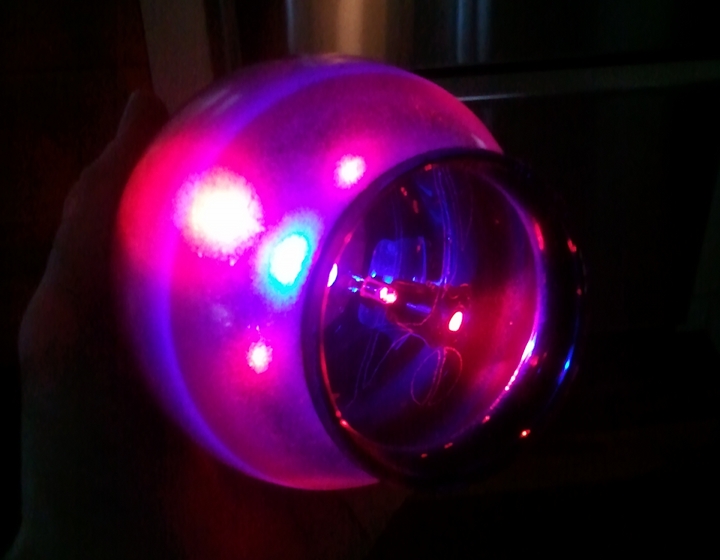
Pulled the power-cord back into the vase (it was a tight fit, so friction is enough to hold it in place) and had the finished product:

Things learned:

  • If I do this again, I’ll put the etching lower on the lamp:  It will be easier to see and show-off.
  • Need to get LED’s that have a wider angle:  These are fairly focused, so don’t diffuse as much in the lamp as I’d like.
  • The lines of the etching itself are very thin:  I’d find a way to make the etched-away areas larger.