Posts Tagged ‘ assembly

Building the C-Bot 3D printer: Part 16 : Assembly Updates

Jump to C-Bot blog index to see all the posts.


While I struggle with getting my Z-steppers to work, I did some frame upgrades:

  • I hadn’t ordered enough of the OpenBuilds ‘Black Angle Corner Connectors‘ : I needed 18, I bought 8 (not sure how I missed that)…  Mason needed extras as well, so he placed a big order, and I got my ten in today.  So, I swapped out my printed corners on both the bottom of the frame, and the parallel arms under the HPB with the new corners.  Metal FTW!
  • The 8x 55mm M5 bolts that held the wheels onto the Z-gantry weren’t long enough:  I couldn’t actually got a nut on the back-side.  Mason experienced the same issue, and picked up two 10-packs of 60mm M5 bolts and gave me one:  I went through the process, one at a time, of removing those bolts from the wheel assembly on the HPB, and swapping it for the new 60mm version, with a locknut on the end.  I held all the existing spacers, wheels, and shims in place (so they wouldn’t fall all over the floor when I removed the bolt) with tape on the bottom:  Worked great!

Thoughts on my Z-stepper issue:

  • The A4988 drivers (that came with my Rumba ) ‘continuous current per phase’ is 1A (see link).  The DRV8825‘s (like what Mason uses) are 1.5A.  I’m wondering if that 50% boost would be enough to lift the z-stage?  I found a 5-pack on Ebay for $13, so those are on order.  But it can take up to a month:  Mason may have a spare, and if so, I can test this out and see if the extra power is worth it.
  • I spent a good amount of time making sure my rear Z-extrusions were the exact width apart, and futzing with the HPB Z-stage brackets:  I can now lift the gantry with one hand with little resistance.  I also made sure the Z-steppers were exactly below the ACME lead-screw holders:  I can now get the HPB to lower, just not raise (without help from my hand).  So again, I hope the DRV8825’s will resolve this lifting issue.

Time tonight:  About 2 hours.


Jump to C-Bot blog index to see all the posts.

Building the C-Bot 3D printer: Part 13 : Assembly Day 7

Jump to C-Bot blog index to see all the posts.


My final day of hardware assembly:  Mason brought in the missing bolt I needed to finish the HPB installation.  I also picked up a pair of ‘Astrosyn Nema 17 Isolation Mounts’ from a friend of Mason’s:  I’m told these can really help with stepper vibration to improve print quality:  I installed them on each of the Core-XY steppers.

On a side note, if you don’t feel like ordering them from England, there’s a guy on a forum here selling them in the US (only).  At the time of this blog he still has some available.

I also got the Core-XY belts ran with the help of my son.  So at this point truly, all the hardware is in place:  Nothing stopping me from the electronics next.

I printed out a case for the Rumba board.  My Rep1 was having a terrible time with extruder jams and extruder skipping.  I’ll probably need to print it again to get better quality :S

Gotchas:

  • When installing the isolation mounts I realized the M3x10mm bolts holding in the steppers in would need to be cut down to 5mm.  So back down to the workshop with the Dremel & vice to cut eight of those.
  • I’d forgot to load the appropriate T-nuts for the Rumba case and control panel (when I finally print it):  So I had to pull off the bottom two legs, load more nuts, and re-measure stuff as I tightened everything up.

Here’s some closeups of the latest:


Jump to C-Bot blog index to see all the posts.

Building the C-Bot 3D printer: Part 12 : Assembly Day 6

Jump to C-Bot blog index to see all the posts.


Today I righted some wrongs of the past, and got nearly all the hardware assembled:

Corrections:

  • Mason updated the ACME block holders and I reprinted both of them for install:  Now the z-steppers and lead-screws line up perfectly vertical.  Nice!  Unfortunately I ran out of the pretty ‘soulful blue‘ filament I’ve been using, so I had to print them in a different color blue.   A nice blue as well, but I was hoping to keep this all the same color.
  • Mason gave me the shim I was missing, so I was able to finish installing the X-gantry/hotend bracket.

New stuff:

  • Got the E3d Volcano mounted to the x-hotend gantry.
  • Mounted the Bowden extruder to the frame & connected the PTFE tube to the extruder.
  • Installed the heated build platform.
  • Printed and installed end-caps for the Z-gantry.

Notes on the HBP install:

  • I’d just eyeballed the location of the paired cantilevered 20×40 extrusions (the ones along the Y axis, which I will now refer to as the ‘Y-extrusions’) that hold the HBP and attach perpendicular to the 20×60 z-gantry:  Of course this wasn’t close to how the HPB wanted to be mounted.
  • The process I used to get it mounted is as follows:
    • I measured the distance from the mounting holes on my HBP:  It’s 12″ square, and the mounting holes happen to be exactly 30cm apart.
    • Starting on the left Y-extrusion, I measured 1cm back from the front to bolt in the first mounting bracket to:  I based this on eyeballing how far forward my hot end could move.
    • From there, I measured back 30cm, and installed the other bracket.  I then repeated this process on the right Y-extrusion.
    • Laying the printer on it’s front, I loosened the bolts holding both Y-extrusions to the z-gantry allowing me to slide them left and right:
    • First, I got them spaced 30cm apart (based on the holes on their previously installed mounting brackets).  Then I centered them by measuring how far away they were from either side of the gantry, and slowing shifting them until they remained 30cm apart, but an equal distance from either side.
    • Righting the printer, I then loosened them up again, and made sure the two end brackets were 30cm apart from hole to hole.  Tighten everything up.
    • From there it was easy to install the mounting springs, bolts, and thumbscrews.
  • Finally, I found a level spot in my house (which is surprisingly hard actually, considering it’s on a hill and built in 1938), and used a bubble-level to “level” the rear z-gantry by twisting the lead-screws.

Gotchas:

  • I ended up cutting up one of M3x25mm bolts to help attach the swinging arm to my Bowdwen extruder:  As it turns out, I needed that to install my HBP:  I only had 4 left.  So I’m short one, but luckily Mason has a spare he can get me.
  • When installing Mason’s new ACME block holders, they were about 3mm deeper than before to compensate for the previously-mention misalignment issue.  The problem is, the bolts I custom cut to attach them were now too short:  More bolt cutting ensued based on the new design.

The only thing left hardware-wise is running the belts:  I’m still waiting for my pullys to show up, but I hope to have them this week.  So the next stop will be electronics!

Time spent: About two hours.

day12

Day 12 progress


Jump to C-Bot blog index to see all the posts.

Building the C-Bot 3D printer: Part 11 : Assembly Day 5

Jump to C-Bot blog index to see all the posts.


Today I knocked out The Y-gantry, and the X-Gantry/hotend.  Total time: About three hours.

As usual, there were some gotcha’s:

  • Somehow, the file that created the print of two plates that the G2-belts and hot-end bolt to was mirrored:  All the files I had, were reversed, so that the belt clamps were in the wrong location (bottom instead of top and vice-versa).  So I had to scale that model and reprint 2x of them.
  • After getting all the X-Gantry/hotend wheel assemblies staged, I realized I was short onemini v-wheel precision shim‘: Either I was shorted one, or I lost one.  Luckily I can trade Mason for some t-nuts 😉
  • From the previous day’s build:  The shimmed angle the z-steppers have to be at to connect with the lead-screws is just too extreme:  Should be perfectly straight.  Either Mason or I will need to update the ‘ACME Block Holder’ stl to ‘push it out’ more & reprint.

Jump to C-Bot blog index to see all the posts.

Building the C-Bot 3D printer: Part 10 : Assembly Day 3 & 4

Jump to C-Bot blog index to see all the posts.
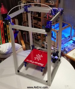

I spent around six hours over two days knocking out the cantilevered build platform and addressing other ‘gotchas’ from previous days:

  • I had totally forgot about the endstops when building the frame:  Since Mason had created his own endstop solution, I ended up having to take a section of it apart and load up the t-nuts for the Z endstop.  When I’m done with the build I’ll show where all the endstops ended up.

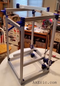
Today’s progress:  cantilevered build platform, dual lead-screws installed, all endstops mounted.  It’s starting to look like a real printer…

day3

Day 3 & 4 progress

Why did it take so dang long just to add the build platform?

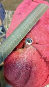
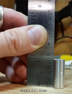
  • I had ordered 8x 40mm spacers that help build part of the built-platform wheel assembly.  But, Mason had failed to notify me they needed cut down to 25mm (it’s all good Mason <wink>).  After much confusion and trying to fit parts together I txt’d him and learned this.  So, it was down to the workshop with my saws-all and files to get some perfectly spec’d 25mm spacers:
    • 25mm_ftwprecision_machined
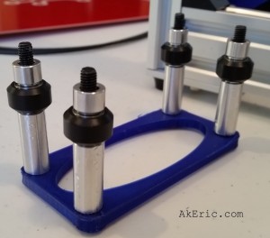
  • Once those were to the correct length, I could put together the wheel assembly.  The order is:  55mm low-profile screw, 25mm spacer (cut down from 40mm), wheel shim, wheel, wheel shim, 1/4″ spacer.
    • z-gantry wheels
  • And with the help of my son holding it all in place, bolted it to the rear z-extrusions.

Other gotcha’s from today:

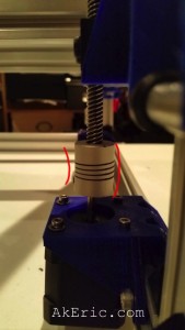
  • After I got the build-platform mounted to the z-rails, the flexible couplings on the Z steppers wouldn’t mate properly with the lead-screws:  A good 5mm off.  I couldn’t find anyway to shim the printed parts, or see where anything was off:  It all looked correct, but wasn’t lining up.  So I ended up adding washers on top of the rear of both steppers to tip them “back”, and line them up with the leadscrews.  This isn’t ideal (since now there is a slight angle between stepper and screw), but for now it will have to do (and is later fixed).
    • bad_angle
  • When bolting the ACME lead-screw blocks through their printed holder into the extrusion (the black bolt-heads you can just make out in the top-middle of the above image), I didn’t have a bolt the correct length:  I had to cut four of the M5x40mm’s down to 30mm so they wouldn’t hit the extrusion.
  • From the image of the wheels above:  When they bolted into the build platform, the bolts don’t stick all the way though the 3d printed parts so a nut can go on the end:  And, two bolts on each side don’t seem to actually grip the 3d-printed holes at all, since the holes are slightly oval.  I feel like if the bolts were 60mm, rather than 55, nuts could be put on the end and this would be a much sturdier assembly.

Jump to C-Bot blog index to see all the posts.