Archive for the ‘ projects ’ Category

New X-Carve project: Soap Dish

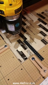
Working with the X-Carve has been a lot of fun.  A while back I 3d printed the “Soap Holder by piuLAB“, and figured something similar would be great to route.

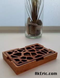
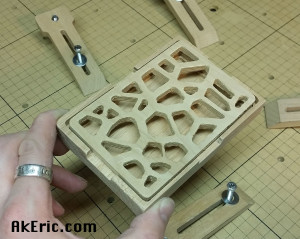
Took some time in Maya generating a pleasing voronoi pattern for the top of my soap dish, which I cut out of alder, and the bottom out of some red oak:

soap_wip

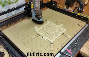
Generated the gcode in MeshCAM, and use Chilipeppr to send it to the X-Carve.  Still a lot of learning:

  • For the top:
    • Used a 1/8″ 1-flute upcut endmill at 120″/min, 1/16″doc, 1/16″ stepover, Dewalt611 at 1.5, based on chipload calculators.  It seemed to cut just fine. but as you can see (if you zoom in) there is vertical banding on the Z.  After posting to the forums, the consensus is I’m cutting too fast.  So… I’ll slow it down next time 😉
    • It didn’t cut all the way though, so I had to use an x-acto to cut out the rest of the pockets.  Either I need to trick it into thinking my material is thicker, or do more tuning on my Z-steps.
  • For the bottom:
    • Used a 1/4″ 1-flute upcut endmill at 120″/min, 1/8″doc, 1/8″ stepover, Dewalt611 at about 2, based on chipload calculators.  It seemed to cut just find as well using a conventional climb cut on the rough pass, but on certain sections I got a lot of chugging.  Again, too fast.  Slower next time.

When it was done I applied some stain to the top, and sealant to both, and came up with this:

soap_final

Not too bad all things considered :)

You can download the STL’s from Thingiverse here for routing, or 3d printing.
Digital to wood : A new X-carve piece

New piece I made on the X-Carve:  It measures just under 12″ square, by 1/3″ thick, birch plywood, with some ‘natural’ stain applied:

final_piece

So how did I get there?

Years ago, like ’98-2000-ish, I was really into building shader networks in Maya.  I loved their ramp shader, so versatile.  Later Maya introduced their ‘layered shader’, which is a lot like a layered file in Photoshop.  Over the years my career in CG has taken me away from shader creation, but I always remember how much fun it was ‘back in the day’.

Fast forward to now with the X-Carve :  I know that I can turn a grayscale height-field into mesh, and MeshCAM will turn it into a toolpath, so this was my first attempt at doing just that, via a shader network in Maya:

shader_network

This visualizes (from right to left) the shading group (which the mesh is assigned to) that has both a lambert (just for mesh visualization) and displacement material (for later conversion to displaced polys) assigned.  They’re in turn both fed by a layered texture, that has inputs from a ramp (on top) that defines the border, an ocean texture (that makes the ripples), and another ramp that makes the circles.  I authored a Python script that automates this whole creation process and mesh assignment, with a simple window so I can repeat this process easily.  Iteration is king.

From there, I had something that looked like this, assigned to a flat, tessellated polygonal plane:

heightField

Which I then converted into displaced polygons (Maya: Modify -> Convert ->  Displacement To Polygons)

polygons

Exported as an stl, and brought that into MeshCAM for toolpath generation as a two-part cut:

  • Rough pass with a 1/4″ two-flute upcut endmill.
    • 60 inch/min
    • DOC .0625″
    • Stepover .125″
  • Finish pass with a 1/8″ two-flute upcut ballnose.
    • 60 inch/min
    • DOC .0312″
    • Stepover .025″ : Should have doubled this to get rid of the scalloping.
  • Had the DeWalt 611 router speed set to 1 on both based on rough chipload calculators:  Seemed to do fine, occasionally had some stuttering on the rough pass.

I sent the gcode to the X-Carve via Chilipeppr, and over the next 2.5 hours watched the magic ensue:

finish_pass

The above pic shows the final pass emerging from the rough.

Until the final product appeared:

route_complete

All the hold-downs are overkill, but I realized I had told MesCAM to machine the entire stock, so I had to move them around as the progressed from bottom to top, or I would have machined the clamps themselves.  Noob move.

Pretty happy with the end-result:  It’s actually quite confusing to the eye in person as the shadows dance around it.  Great test though, and a lot learned.

C-Bot 3D Printer: Supercharging the Volcano

Jump to C-Bot blog index to see all the posts.


When I installed the 1.2mm E3D-v6 Volcano nozzle, I noticed that when my PLA cooling fan kicked on, the hotend would have a really hard time maintaining temp running at a ‘high’ (45mm/sec) extrusion speed (for the Volcano):  If starting at 220 deg, when the fan would kick on it would just drop and drop, and I’d stop the print or kill the fan when it hit 200 deg.  If I dropped the speed down to say, 10mm/sec, it could keep up.  This made me think fan+cold filament was too much for the hotend.

After much discussion on Google+ (here, and here), I tried a variety of things, none that got it working 100%.  I re did the Marlin auto-PID with the fan on full blast:  This got it to the point the temp would drop some 10-15 deg, then slowly creep back up.  But this is far from optimal.

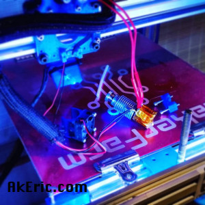
The thing that tipped me off was the suggestion to figure out what the power is of the heater-cartridge in my Volcano hot-end:  Measuring the resistance gave me 7.1 ohm, which equal to 20.3w (voltage^2 / resistance = 12v*12v/7.1 = 20.3w).  Checking online, I noticed that there are 40w heater cartridges as well, so I picked one up (I got that one simply because it could be shipped via Amazon Prime…).  Installation ensued:

volcanoUpgrade

And that my friends, is the secret sauce:  After I got the new heater cartridge installed, I re-ran the PID-Autotune in Marlin (via Simplify3D)…

M303 E0 S200 C8

…waited a number of minutes for it to finish, then crammed the three values back into my Configuration.h, uploaded that via the Arduino IDE to the Rumba, and I was in business:  Not only does the hotend heat up faster now (220 deg in 1min 50 sec with full fan compared to 2 min 30 sec with no fan), but I can maintain hotend temp with 100% 24cfm fan kicked on.  It’ll drop maybe 3 deg when the fan blasts on, then pull right back up to temp.

So a note to any of you Volcano users:  Make sure you have the 40w heater cartridge (the one with the red leads) not the 25w one (blue leads).

I measured the new heater before I put it in:  4.1 ohm resistance, which equals 35w, not 40w.  But it works, so I’m happy :)

Another thing learned:  When you issue a M105, and get something like this back:

RECEIVED: ok T:206.1 /220.0 B:26.0 /0.0 T0:206.1 /220.0 @:127 B@:0

The @:127 is the ‘power’ going to the hotend.  Note that 100% = 127, not 255, in this instance.


Jump to C-Bot blog index to see all the posts.

Making The OneHundred

I always found it, humorous, when some Instagrammer got ‘X number’ of people and made some crazy post about it:  “LOVE you all, hugs and kisses”, etc.  I recently hit 100, and figured this would give me a good excuse to combine both my 3d-printing and newfound CNC-routing skills:

I’ve been wanting to do a piece that combined both 3d printing and CNC routing, some came up with idea of a routed background, with 3d printed text.  “The OneHundred” was thus created:

beautyShot

Info on the techniques used to make it:

3D Modeling

The model was created in Autodesk Maya:  I wrote a super simple tool to randomize the rotation and position of simple poly cubes that made up the background.  A 3d model of the text was generated, and Booleaned out of the background.  An stl was generated for both the background, and the text.  The piece is 12″ square, by 3/4″ deep.

3D Printing

The text model was sliced using Simplify3D, and printed on my C-Bot directly off the SD card (I recently was printing something via Octoprint, bumped the RaspberryPi, and it lost USB connection half way through a multi-hour print… don’t like that at all).  Settings:

  • Filament: Makergeeks Orange PLA
  • Extruded @ 230deg (hot for PLA, but per manufacturer recommendation), bed @ 60 deg
  • 1.2mm E3D-v6 Volcano nozzle
  • 600 micron layer heights, 1 shell, 20% fast hexagon infill.
  • Print speed is 45 mm/sec : Sounds slow, but that’s a volume of 32.4 mm3/sec extruded.  For those keeping score, a the volume extruded of a .4mm nozzle with 200 micron layer heights at 90mm/sec is 7.2 mm3/sec:  Volcano is printing 4.5x as fast, crazy.
  • Took about 1.5 hours.  (so, based on the above specs, it would have taken 6.75 hours on a ‘normal’ printer).

CNC-Routing

MeshCAM was used to generate the toolpath cut from the MDF background.  The gcode was sent via the Chilipeppr GRBL workspace.  MeshCAM settings:

  • Roughcut:
    • 1/4″ 2 flute upcut endmill
    • DOC: .0625″
    • Stepover: .125″
    • Feedrate: 60″/minute
    • Took about 1.25 hrs
  • Finish Pass:
    • 1/8″ 2 flute upcut ballnose
    • DOC: .0312″
    • Stepover: .025″
    • Feedrate 60″/minute
    • Took about 3.25 hours

The above settings are completely based on previous trial and error, and could be improved no doubt.  Things I noticed while cutting:

  • Got some chatter on the roughcut, even when I turned up my DeWalt 611 speed all the way.  Guess I was cutting to aggressive.
  • The final piece has more scalloping than I’d like:  Think I need to lessen the stepover next time.
  • Having to babysit the machine for 4.5 hours was… not fun.  But I got to read some magazines I needed to catch up on.

Final Thoughts:

Great learning experience, I’m really getting the two-cut process down using my touchplate.  Can’t wait to do more!

X-Carve : Designing a dust shoe for the DeWalt 611 Router

Disclaimer:  3d printing and/or using this material in any form releases me from any liability:  Use at your own risk.  I will not be responsible for any damage to person or property based on use of this material in digital or physical form.


(now that we have that out of the way…)

Intro:

While there are a number of ‘upgrades’ for the Inventables X-Carve I’ve read about, the most important one to me is a dust collection system.  There were a couple of options I found on the forums, but none that fit the 2.5″ line I wanted to use to hook to my Rikon Dust Extractor: It actually has a 4″ hose coming out of it, which I step down to 2.5″ into my Oneida Dust Deputy, then run another 20′ over to the X-Carve.

After a couple weeks of modeling in Maya (not necessarily a CAD modeler, but I make tools in Python as I need them to suffice), printing prototypes on the C-Bot, I finally have something functional:  v.A05.

I wanted to provide this to the X-Carve community as a big thank-you to all the forum peoples that helped me along the way.

If you make one for yourself or anyone else please:

  • Give credit.
  • Make for friends, but don’t sell it for profit.
  • Please reference the CC Attribution Commercial 3.0 license.
  • Feel free to improve, but see above.

If you’d like me to print one for you, contact me (warpcat at gmail dot com) for cost & shipping.

A shot of it disassembled:

final_proto

Prototyping:

It was (as expected) quite a learning experience, and I went though a number of revisions to get to this point:

prototypes

Prototypes from right to left:

  • Initial wood prototype cut on the X-Carve.  Very quickly I realized that I know a lot more about 3d printing than cnc routers.
  • Blue #1 : Rough 3d shapes, good starting point.
  • Blue #2 : More stylish, actually functional.
  • Grey #1 : I started doing two-part cuts with tool-swaps, and realized that I should have a quick release.  This one has the vertical slotted section held in place by four powerful magnets to the main body.  Technically works, but has too much play and slop.  Also has a groove in the bottom for the strip brush.
  • Grey #2 (mounted to the machine) : Current iteration.  No quick disconnect, but very rigid, and easy to remove the two screws.

Features of v.A05:

  • Connects firmly to left side of the spindle mount, using 2 bolts.
  • Tapered hole for the 2.5″ line, allowing for friction-fit of the dust-line.
  • See-through window providing visual access to the bit, and for the dual-lights of the DeWalt 611 router to shine through.
  • Groove in the base to allow for the insertion of a strip brush.
  • Allows for adjustable height to better fit your bit length.

Bill Of Materials

  • 3d Printed Dust Shoe.  Download the stl on Thingiverse here.
  • Clear acrylic for the window.
    • I bought a sheet of 2.5mm / .0975″ Lexan at Orchard Supply Hardware that worked well.  Could double that thickness and still have room.
  • 2″-ish Strip Brush.
    • I used this “Easy Cut Strip Brush” from McMaster-Carr.  You’ll need a little less than 17″ for the perimeter slot.
    •  What you get is up to you, but I’d advise on getting the softest possible bristles.  The bristles for the listed brush are too stiff IMO, FYI.
    • See specific notes below on issues with this.
  • Hot Glue
    • For strip brush and window adhesion.
  • 2 M4x12 Socket Head Cap Screws.
    • Used to bolt the print to the router bracket.
    • McMaster-Carr Link
    • I bought mine at Orchard Supply Hardware.  10mm would probably work fine too.
  • 2 washers.
    • For the above M4 screws.
  • 2.5″ Swivel cuff hose attachment.
    • I got mine at brick & mortar Woodcraft (can you believe it was cheaper than Amazon?)
    • Swivel is important to allow the hose to not bind in the shoe.
  • A bunch of 2.5″ hose to connect to your dust collector.

Build Instructions

  • 3D print the dust shoe stl file:  I would highly recommend to print this as strong as possible.  If you’re using a .4mm nozzle, I’d do 3-4 shells, 25-50% infill.

(This video was actually of one of the prototypes, but you get the jist)

  • Carve the acrylic window on your X-Carve.  Easel file here.
    • Note, as modeled, the diameter of the larger dual circular apertures is 6.5cm each.  As printed on my C-bot, they are 6.4cm each.  I designed them in Easel to be 6.3cm, and it fit perfect after cut.
    • cutting_lexan
    • I used a 1/8″ single flute up-cut bit, default Easel settings for that material, DeWalt 611 speed of 1.
  • Cut your strip brush to length, and insert into the channel on the base of the shoe.  But first, read the below notes.
    • Super important notes on the strip brush:
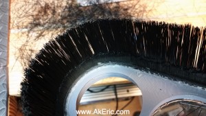
    • Based on the version I purchased and listed above, I found that the bristles were far too stiff, based on the number of them.  Because of this, as the toolhead would change direction, the pressure of the bristles on the head would actually lift it on z during movement change.  Not so good.
    • Suggestions:
      • I ended up cutting out 3/4 of the bristles, on the inside of the strip.  If you go this route, I advise you do this before you mount it:
      • cutting_bristles Cutting in-progress.
      • Buy much softer bristle strip.  I’ve seen horse-hair as an option, that may work well.
      • Cut the bristles shorter.
    • Based on how I designed it, the strip was easy to fit into the side channels, and I used a screwdriver to help ram it into the turns.
  • Use hot-glue to run a bead around the inside of the strip-brush & dust shoe to stick it in place.
  • Mount the window in the top of the dust shoe, and run a bead of hot-glue around it’s perimeter to stick it to the shoe.
    • Note, a heat-gun will soften the glue for removal if needed.  Just don’t damage the print.
  • Slip the shoe over the bit into the router mount, and attach with the M4 socket screws & washers.  I use two.
  • If you haven’t already, screw the swivel-cuff into your 2.5″ line.  Then press it into the hole in the shoe, slightly twisting to get a good friction fit.  Be sure to hold the shoe from the bottom during insertion, not the vertical side piece, so as to not torque the print too much.  If you have any concern of this fit, you can run a bead of hot-glue around it too.

Use Instructions

  • Raise the shoe up as far as possible to get the bristles level with, or slightly higher than the bit.  Be sure to not block the down-vents from the router with the window:  Give it some space.
  • Be sure nothing can collide with the shoe, specifically material clamps.
  • While running it, check how much pressure is being put on the bristles:  Make sure they’re not causing any binding.  Trim as necessary.  Or buy softer bristles.

Specs:

These are as designed, not necessarily as printed.

  • Width : 105.5mm
  • Height : 178.4mm
  • Depth : 124.9mm
  • Strip-Brush channel:
    • Width: 6mm
    • Height: 5mm-ish
    • Note the channel is rotated 10deg, so the brush will flare slightly out.

Future Improvements:

  • I’d still like a better quick-release for swapping bits.  Removing the two screws isn’t hard, but I’d like it to be “more slick”.
  • I need to find a better solution for the bristles.  Either softer, or less of them (I may have more cutting ahead of me).

But for right now, I need to actually start making stuff on the X-Carve, rather than for the X-Carve :)