Archive for the ‘ projects ’ Category

Designing an extruder cooler for my Replicator 1

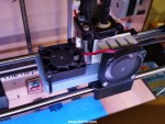
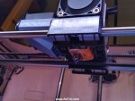
I purchased my Makerbot Replicator 1 nearly three years ago.  I don’t think at that point it was wide-spread knowledge that PLA likes to be cooled as it extrudes and  thus, no extruder cooler.  Most modern PLA printers have these standard.  Up until now, I’ve pointed a desk fan at my prints to provide cooling.

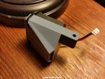
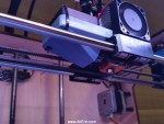
This weekend I decided to model up (in Maya) a fan mount to use as an extruder cooler:  Works great, uses the stock hardware so nothing new (other than the fan) is needed.  I use a removable glass build plate affixed with springy metal clips. These clips stick up off the build platform and will hit anything slightly lower than the gantry. Because of this, I designed this to shoot a jet of air just below the tip of the nozzle, but keeping the whole apparatus above the base of the gantry.

Download the model and get install directions over on Thingiverse.

[sketchfab id=”9e317b81ac7342dea61df0332dad8a28″]

3D Printer Surgery: Replacing my Makerbot Replicator 1’s Voltage Regulator

I purchased my Makerbot Replicator (1) when they were first released, nearly 3 years ago now.  Other than a few hiccups (HBP cable failing repeatedly, and a dead botstep needing replaced) it’s ran like a champ.  Reading the forums like I do, I’ve seen a number of people talk about their voltage regulators dying (the LM1084), and killing the whole board in the process.  I don’t know when I’m going to upgrade, and I’d like to keep this machine running as long as possible, so an update was in order.

Makerbot users are always a super-helpful bunch, and the folks over at the Makerbot Users Google Group are no exception.  I’d seen a lot of posts on the subject, but none that really broke down specifically what needed to be done, and what parts needed to be sourced.  So I asked, and they answered.  Armed with that knowledge (and this great photoset by JetGuy) I ordered from Digikey a “Recom Power R-78E5.0-0.5” voltage regulator (the 5v version, not 3.3v) based on user tramalot’s recommendation.  Below are the overall steps I took to install it.  It’s not hard once you grasp what needs done, and my hope is this breakdown can help others in the same situation.


First I sketched out the old and new wiring on paper:  The new regulator has a different pinout:  Everything has been shifted one pin left.

Next I snapped a pic of the Mightyboard pre-removal as a sanity check:
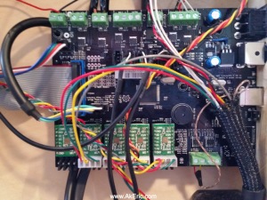
board_before

I made sure to ground myself with a wrist-strap just to be safe.

I then labeled all the wires with little stickies, unhooked everything…
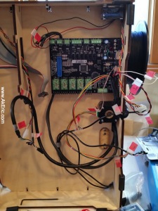
spaghetti(note, this is actually the board on reinstall, but it’s all the same)

…and removed the board.  Here’s a shot of the bare board, and the new voltage regulator:
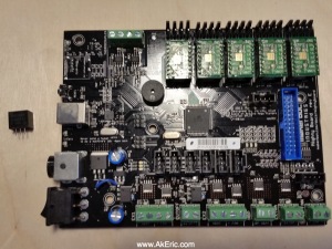
board_and_reg

Like discussed in the forums, I used snips to cut the leads from the old voltage regulator.  I then took my soldering iron (the big, red, hand-held kind), and pressing it against the back of the reg, waited for it to desolder from the Mightyboard.  I lightly twisted the reg back and forth with a pair of pliers at the same time since I had no idea if just the pressure from the iron would move it.  It took a lot longer than I expected, and at one point I thought it wouldn’t work at all.  I’m guessing I had to hold it from 5+ minutes.
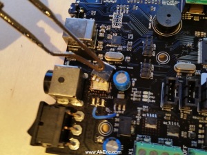
desolder

From there I desoldered the old remaining leads, and soldered in the new voltage regulator using wires to aid in the pintout offset.    I liked what JetGuy had done in his Flickr post, so I hot-glued it to the power receptacle for extra stability:
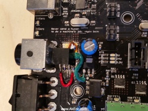
newInstall(Note the brown/orange cruft is just left-over flux)

Put it all back together, and I was relieved when it turned on, and printed successfully.

I figured while I had it apart I should provide for some extra cooling, so I drilled out a 1.5″ hole right by the Mightyboard fan.  However, after I did this I had more conversation on the above forum linked above, and learned that the Mightyboard really needs no fan cooling at all.  But… having it there should’t hurt.
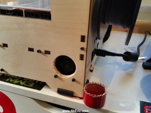
newVent

Hope this gives my rep1 many more years of good printing :)

My thanks again goes out to the Makerbot Users Google Group users JetGuy, tramalot, and Joseph Chiu for their helpful advice!
NinjaFlex!

A number of months ago I picked up some Fenner Drives NinjaFlex (via ToyBuilder Labs):  I was really excited to give it a shot, but was unable to get it to load into my Makerbot Replicator (1) :  I’d done the drive-block upgrade long time back that should enable me to successfully extrude it.  After disassembling the extruder I’d watch as the filament would enter the thermal tube, then after some time bulge out the (really, really small) gap between the thermal tube and drive block.  I figured the extruder wasn’t getting hot enough, but the onboard firmware didn’t let me adjust the filament load temp, only the pre-heat temp:  I could pre-heat plenty hot, but it would cool back down (to an unknown temp) before doing the filament load.  Frustrating, and I had to abandon it.

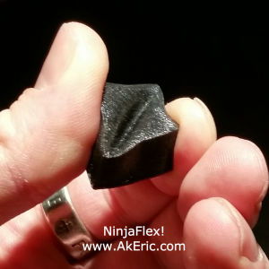
Back in December I upgraded my firmware to Sailfish.  And today it dawned on me that Sailfish lets you adjust the pre-heat temperature.  Armed with this knowledge, I cranked it up to 240c, and it loaded without a hitch.  The resultant is this magnificently squishy 2x2x1 cm half-cube:

ninjaFlex

It was sliced in Simplify3D and printed with these settings:

  • Extruded at 240 deg onto an unheated build platform covered in blue painters tape.
  • 2 shells, 4 floor, 4 roof, 20% infill, 200 micron layer height.
  • 30mm/sec extrusion (per all the online specs I’ve read), 120mm/sec travel.

New 3d Print: Oahu

After making my SF Bay print, I thought I’d turn to the Hawaiian islands: I lived on Oahu for a time and have many fond memories. I was always shocked by its beauty constrained by size: I’m pretty sure you could drive around it twice in one day if you tried.  Printed on my Makerbot Replicator (1) .  Download the files to print over on Thingiverse.

I’ve covered in detail the process I used to make these maps.  But below are tweaks I made this time:

  • I printed the ocean much thicker:  The bay print was 2 layers (.4mm) but this just seemed too delicate.  The oceans for this were 8 layers (1.6mm).
  • I had issues with the corners of the bay print lifting during print.  For Oahu, I set my build platform to 50 degs:  This printed them completely flat, with no warping.
  • The stl’s that Terrain2STL generated had some pretty big holes in them:  Mainly along the sheer cliffs that Oahu has.  I’m guessing this is data that couldn’t be captured successfully from space.  Unfortunately these were bigger holes than Meshlab could cleanup successfully.  Luckily, running them through Microsoft’s “Model Repair Service” (used to be Netfabb Cloud) fix each one up nicely.

Check out the article written on it at 3DPrint.com

How To ‘Print The Bay’

Several people asked me if I’d share the specifics of how I completed my previous print, “Print The Bay“.  Sure!

ptb_front

As mentioned in the post, I used a great (and relatively new tool) by Thatcher Chamberlin called “Terrain2STL” to do the heavy lifting of the map geometry creation:  I had looked at the well documented techniques by Thingiverse user Shapespeare (aka Whitney Potter, as documented on his “Grand Canyon” thing here) and was about to start, but discovered several pieces of the software chain were PC only:  I’m currently on Mac.  So while I started trying to figure out an alternate pipeline, I found a random blog post on Terrain2STL, and everything changed :)  With Terrain2STL, it’s as easy as defining a region in Google Maps and hitting “download” to get a 3d printable stl of the terrain (although as mentioned below, some work is still needed).

After doing several test prints I got in contact with Thatcher, making suggestions as I became more familiar with the tool.  One of which was a way to add “extra thickness” to the ground, and the ability to “lower” the water:  In places like the San Francisco bay, much of the land is at sea level.  When I’d print the map, you couldn’t tell where the shoreline was.  Thatcher was able to implement these new “drop” features, and created a special “Bravo” page for Terrain2STL that exposes them.

Based on all that, here’s the overall process I used:

  • Terrain2STL has a maximum capture volume (the red box it creates):  Looking at the map in the software, at maximum capture size, it would take four regions to grab the area I was after (mid to south SF bay).  It has restrictions though:  The capture volume can’t cross over any major grid lines, so I was also gated by that spec.   Since there’s currently no accurate way to do multiple captures exactly next to one another all at the same time, I’d eyeball each red capture box next to one another, using landmarks on the map (usually street labels) to line one up to the next.  When exporting the data, I set “Base Height” to 4, and “Water Drop” to 2.  For any future ones I do I’d probably set this to 8 & 4, simply to make the printed water a bit thicker.  After download, I had four new stl’s on disk.
  • The stl’s aren’t perfect though:  Thatcher has been working on improving the quality of the data, but I still found a couple issues with them:
    • Holes in the data:  You need water-tight stl’s for printing, and these unfortunately weren’t  (Thatcher mentioned the datasets the tool pulls from has ‘holes’, the tool just emulates what it finds).  Trying to keep my toolchain free/open source, I turned to Meshlab:  It will easily fill in holes.  After bringing the stl into meshlab, access ‘Filters -> Remeshing, Simplification and Reconstruction -> Close Holes’.
    • Wrong aspect ratio:  When creating captured regions, based on what part of the world you’re in, the red capture region will be square (at the equator), or more rectangular the closer to the poles you get.  However, the download stl data is always square.  To fix this, I took a screenshot of one of my capture regions, cropping it to the exact size of the red rectangle.  I then pulled up the resolution info from it (on Mac you can RMB on the file and do a “get info”), divided width by height, and I got my scale value.  To set the scale, in Meshlab access ‘Filters -> Normals, Curvature & Orientation -> Transform: Scale’. Turn off ‘uniform scaling’, and set the X axis scale value to the computed aspect ratio.  Optionally you could scale it in Blender (below).
    • Verts stretching below the ground : It can be hard to notice when zoomed out and looking at the mesh in 3d, but on 3/4 of them there were several verts that were slightly lower than the base plane.  When brought into your slice software and dropped on the build plane, this causes the bulk of the mesh to be one or more layers above the platform, and it won’t stick well at all when printed.  Again, trying to keep the toolchain open source, I turned to Blender: Importing each STL into Blender, I switched to the front and side views, and scanned the bottom edges of the mesh:  Any verts that were too low I simply selected and moved back up above the base layer.  I then re-exported them back out as stl.
  • With the stl’s ready for print, I brought them into my slicer (in my case, Makerbot Desktop) and set them to maximum size.  Since I was going for a translucent effect on the ocean, I did a pre-slice preview to see how many layers thick the ocean was (in this case 2 layers), and set the firmware to pause at that height for a filament change.  I started the print using translucent ‘Neon Blue’ PLA, then swapped to a light gray PLA to finish.  Each region took 2.5-3.5 hours on my Makerbot Replicator 1 (Sailfish firmware).
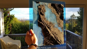
  • To show the translucency of the ocean I had a custom piece of transparent light blue acrylic cut at TAP Plastics (I live close to one making it easy).  While I was there I picked up two tubes of epoxy that dries clear.  After cleaning the prints and acrylic I slathered a bunch of epoxy on the back of each map region, and pressed them into the acrylic, leaving it to set up for a few hours .
  • I wanted to add additional relief to the mountains.  To do this I shot matte-black spray-paint directly onto the mountain regions, and then quickly wiped it off with a rag soaked in lacquer thinner.  Since this is PLA, there is no reaction with the thinner (ABS would be another story…).

I waited for the sun to rise, and shot the above image.  Hope you find this helpful, and let me know if you have any questions.

Check out the article written on it at 3dPrint.com.