3D Printing, step one…
Back in March I received my Makerbot Replicator after a two month wait (new product, backordered). I’ve been trying to get around to post about it, but the (first) Replicator was fraught with multiple problems. I won’t get into the specifics, but I will say that the Makerbot support personal were very accommodating with helping me resolve the issues, and last week my replacement arrived, fully functional. The original one I received was a “dual extrusion” model, meaning it could print two alternating colors. But many of the problems I encountered stemmed from this tech, so I ultimately decided to get the single-extrusion (single color) model.
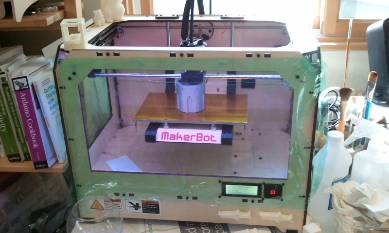
The Replicator doing it's thing: I covered it in plastic-wrap to help cut down on drafts, that can have an effect on print quality. It's print volume is 8.9" x 5.7" x 5.9", or just under 300 cubic inches.
—-
The first thing I get asked is “what are you going to do with it?”, which is still a question I ask myself. I think back to two points in my past, and how they changed my future:
The first was in the mid 80’s when my family purchased an Apple ][c. Up until that decade, computers weren’t popularized in the home, and I feel that was a major turning point for many people: You survived just fine without one, but once you started using one you couldn’t imagine life without it. Extrapolate forward to the internet and I think anyone would have a hard time disagreeing with it.
The second was when I finally wrapped my head around ‘Object Oriented Programming‘ while learning Python & Processing: Up until that point, all my programming had been ‘functional‘. I’d always heard about this ‘OOP’ stuff, but couldn’t grasp how it would help me. But just like the old Apple, once I started using it not only I couldn’t imagine programming without it, but I was able to program much more complex systems.
I see 3D printing possibly falling into this category: I currently don’t envision a wide-spread practical use for it in my daily life, but I have a strong inclination that once I understand the technology and integrate it into my routine, it will find a home among those concepts of the past that have shaped my future. Or, it will be a very expensive door-stop.
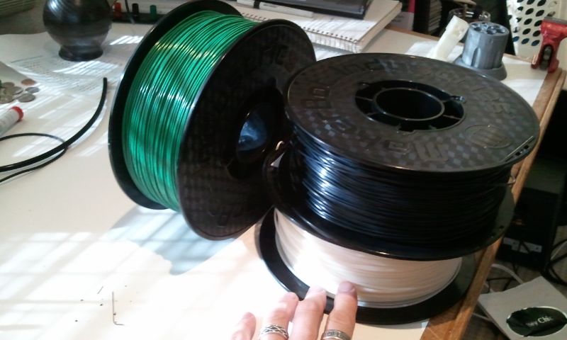
The second thing I get asked is ‘how does it print?’. There is a variety of 3d printing tech out here, and this style of printer does what’s called ‘extrusion’: It squeezes a line of 1.8mm ABS filament (ABS is the same plastic Lego’s are made out of) down through a heated nozzle (220 deg C) out of a .4mm tip onto a ‘heated build platform’ (HBP, at 110 deg C). Before the print started, a 3d model was ‘sliced up’ into individual layers, and the printer will print each layer, one on top of the next by extruding down lines of this filament. Each layer sticks to the one below it. When you’re done, you have a physically modeled 3d object in ABS plastic.
—-
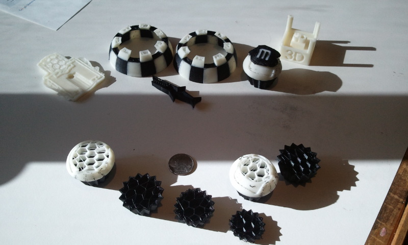
To start learning the system, I’ve been printing designs that came with the printer, and interesting items I’ve found on Thingiverse. If you want to keep track of the things make\like\design, you can checkout my profile there. Or, you can just look at this current picture:
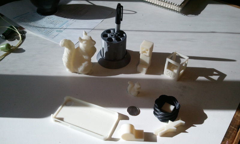
Successes include: Big squirrel, tiny squirrel, revolver pencil-holder, 'Minecraft Creeper', 3d printer, iPhone case, whistle (very loud), shark, twisted shot glass (with calibration cube inside).
I’ve also had a lot of failures, mainly based on the two color printing. Below is an informative pic. What it does show off however, is the hexagonal ‘infill’ pattern that is automatically generated by the software. This both provides support for the item, and helps when printing the ‘tops’ of things:
—-
The next step is to make my own items to print, and there is a lot of software is needed to pull it all together (going in reverse order of usage):
To generate the ‘G-code‘ files the 3d-printer will access to create the print, I use ReplicatorG: This tool only officially opens stl files, so I have to make sure whatever model-generating solution I use can export to the stl format, or I need mesh conversion software. ReplicatorG can be used to do simple transformations to the mesh to fit the print volume: Translate, rotate, scale, and adjusts the print settings: what percentage of ‘infill’ the object has (how solid it is), filament feedrate settings, etc.
To deal with mesh file format conversion from the source data to stl for ReplicatorG, I use MeshLab: It seems very capable in converting one file format to another, and can help ‘clean up’ holes in the mesh.
To modify mesh I didn’t create, I’m starting to use MeshMixer: Most commonly it’s used to help generate a flat base on the mesh for printing. There is a good tutorial video on this here.
Finally, you need software that will generate the thing you want to print. You can design 3d items two main ways: One is to model it in 3d, the other is to procedurally program the model. I want to do both actually:
The 3d modeling approach: I’ve been using Maya (at work) since it was released, and am very comfortable modeling in it. However, it’s a $5k piece of software, so some other home solution is needed. The Makerbot page “3D Design Software 101” does a good job of providing an overview of which (affordable) software one can choose, and where to go from there. I have experience with SketchUp, so that’s the software I’m current investing my modeling mindshare in.
On the procedurally modeled approach, my current plan is to use Processing extended with the libraries HE_mesh and/or toxiclibs: They are both add-on libraries for Processing to make dealing with mesh a lot easier, and can export to the stl file format. I’d love to do all this with a Python implementation instead, simply because I like the language more, but it’s hard to beat Processing for its ease of use. Another option would be OpenSCAD, but I don’t know if I’m up for learning another language right at this moment.
—-
So to date, what have I learned?
- Large items with a flat base don’t need to have a ‘raft’ printed first. But if the item is small, or the base is some crazy shape, a raft really helps.
- Always set the HBP (heated build platform) to 110 deg (Celsius): ReplicatorG likes to set it to 100 deg by default. If you don’t, you could get print edge curling.
- Knock off any hanging filament before the print starts: It can screw up the initial extrusion and cause it not to stick to the HBP.
- Print directly from the SD card, not over usb: I’ve had usb ‘screw up’ a couple times, canceling the print.
—-
What is next? Modeling in 3d, printing my own designs. My ultimate goal is to cast these in aluminum via sand-casting (see my previous post on melting metal). Honestly however, the hardest thing is just figuring out what to make… when you can make anything.
