Jump to C-Bot blog index to see all the posts.
Update: Since authoring this post I have switched my electronics to RADDS, and my firmware to Repetier. See the “Part 31 post” for the latest on it.
Total time: about 3.5 hours.
My Rumba board originally came with 6x A4988 Motor Stepper Drivers that have a 1/16 microstep resolution (I won’t pretend to know that that really means. Sounds small). Their ‘continuous current per phase’ is rated at 1A. I’d had previous problems trying to drive both my Z-steppers off a single driver, so I switched to a driver per stepper. In the meantime though, I ordered a five-pack of DRV8825‘s: They have 1/32 microstepping resolution (ooohh…) and their ‘continuous current per phase’ is 1.5A (which I figured may be enough to drive two z-steppers, which is how Mason does it).
My thought was go back to the ‘single stepper driver controls two steppers’, but since I’ve already got my paired steppers and drivers working, I’ll just leave it that way for the time being. I may only never need to change if I decide to go to dual-extrusion.
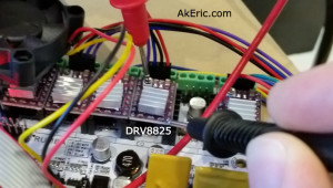
Removing the A4988’s and swapping in the DRV8825’s was seamless: I didn’t even need to flip any of the dip-switches living under each driver, on the Rumba: In both instances, {on,on,on} was exactly what I needed set. However, it’s VERY IMPORTANT you mount them the correct direction (see below pic): The trimpot on the DRV8825 mounts 180 from the A4988: Towards the ‘top’ of the board, rather than towards bottom. I figured this out my checking the silkscreen on both the boards and (luckily) realizing the difference. DRV8825: Trimpot over capacitor. A4988: Trimpot away from capacitor.
Like before, I needed to tune them. Previously I tuned them by adjusting their resistance (rather than voltage) values while they were un-plugged from the Rumba. Later I found these values to be off, and ended up manually tuning them via the trimpot while driving the steppers back and forth. Second time is always better, and I grasp the whole process more fully:
This post from the RepRap Wiki spells it out pretty plainly: To set the reference voltage, you take 70% of the steppers current, and divide by two. So the maths:
How to actually tune it? They have a nice pic on the above link, but the steps I went though were:
- Turn on the Rumba. I then energized the stepper drivers by manually driving the x\y gantry from the LCD.
- Once energized, I set my multimeter to volts, touched the positive probe to the trimpot, and the negative lead to the negative pin on the driver itself.
- From there, I’d adjust the trimpot slightly until I got to around .58v on each.
-

Checking the DRV8825’s reference voltage: One probe on the trimpot, the other on negative.
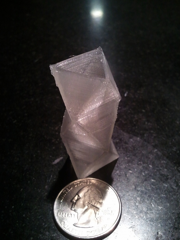
When that was done I thought I’d try and print the calibration cube again: Suddenly everything started printing 2x as small.
AH! A4988 drivers have 1/16 microstep resolution, but the DRV8825’s have 1/32 : You need 2x the steps to go the same distance. So it was back into Marlin’s Configuration.h file to retune the ‘DEFAULT_AXIS_STEPS_PER_UNIT’ variable. By default I doubled everything to: {200, 200, 800, 300}, then individually started tuning them via the process I used before. My final numbers:
#define DEFAULT_AXIS_STEPS_PER_UNIT {199.7403, 200.5415, 804.90995, 300}
Noooow, I can get back to final wiring and tuning my print settings…
Jump to C-Bot blog index to see all the posts.


